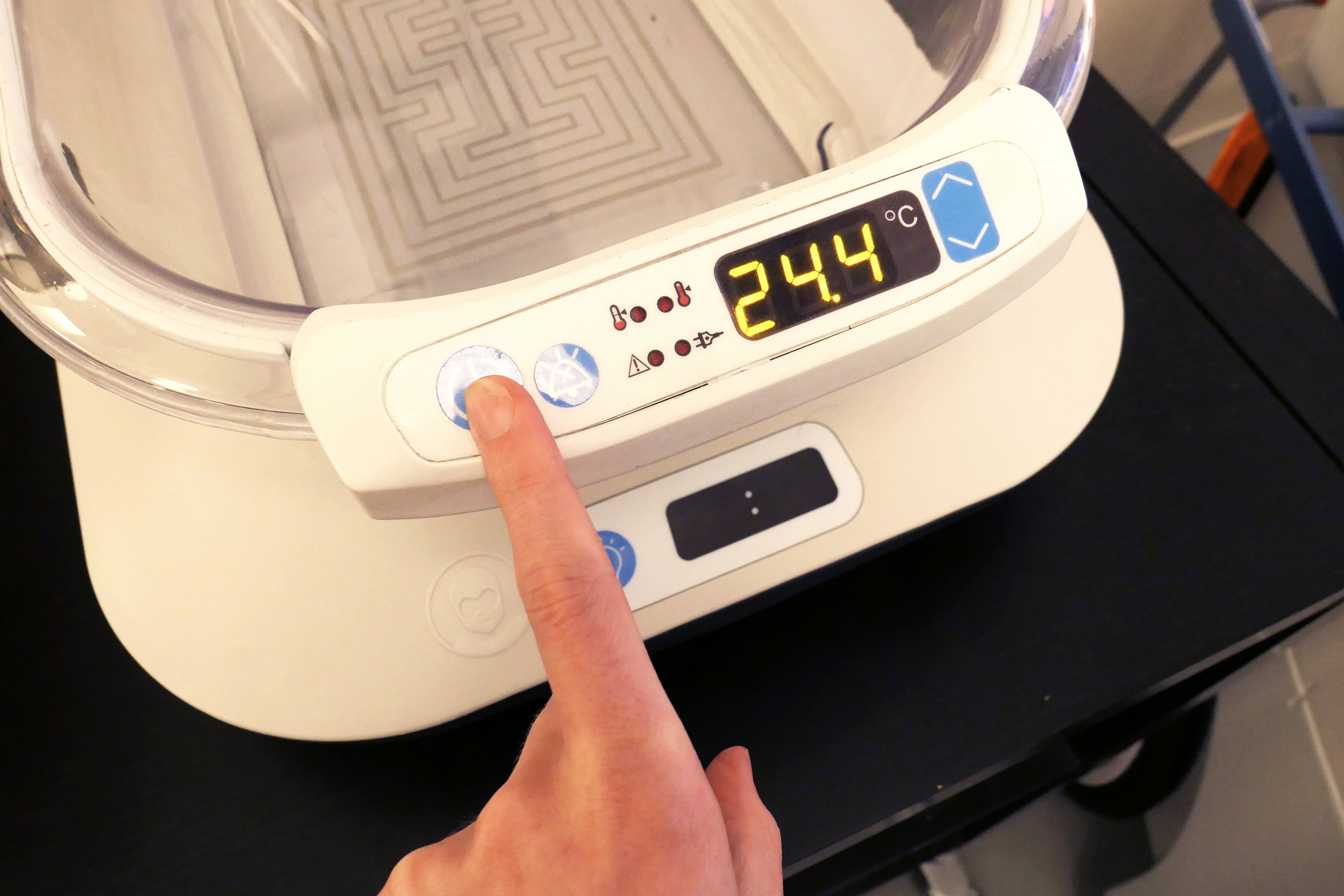

For this summer’s alpha prototype project, we were most excited to implement a new UI design to the Otter Warmer. Firefly, Otter’s sister device, has a membrane switch UI with blue domed buttons labeled with CE mark icons and a tinted window atop a 7 segment display. We designed Otter to match.
Prototyping the membrane switch was a new challenge for us. Using the machines we have in-house, an Othermill CNC, a 3D printer, and a home InkJet printer, we were able to fabricate a UI that looks and works like a real device.
We started with a design in Fusion 360.

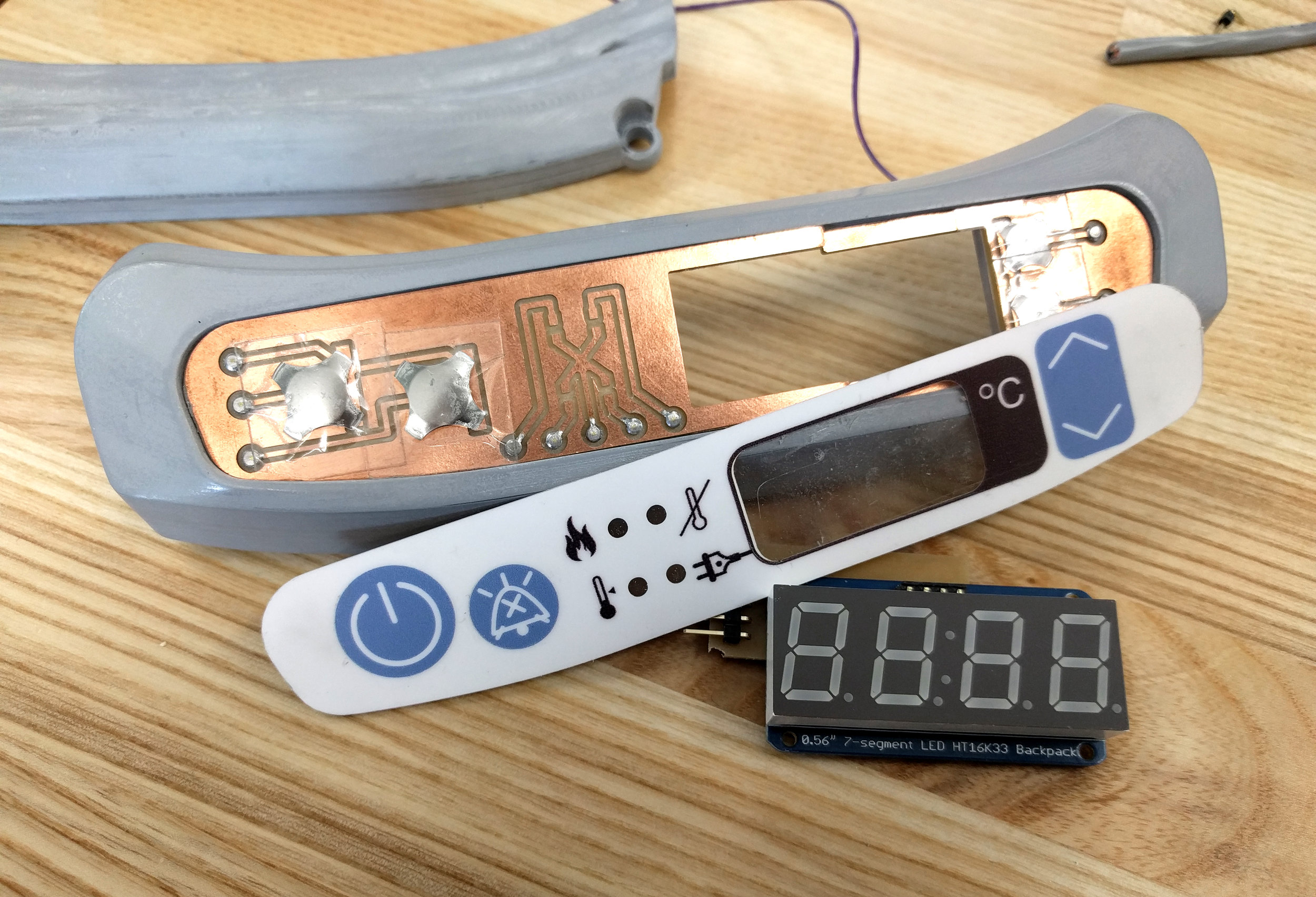
Once we settled on the UI elements to include and the layout, we took that design into KiCAD to build out a circuit board. Each UI element has a dome switch or surface mount LEDs beneath it. We routed traces from each of those elements to an edge where the board would be connected with the full Otter circuit.

The designs were exported in two parts: the KiCAD traces as GBR, and the Illustrator outline vector as SVG. We found that you have more control in OtherPlan, the Othermill software, over the order in which the Othermill runs through your G-code if you import each pass (traces, holes, and outline) separately.
We cut our design into FR1, a “circuit board blank” made of a composite material laminated with a thin layer of copper on the top surface. The Othermill cuts about 2mm deep into the board around a predetermined path, isolating a copper trace from the rest of the board. This allows us to control and send current to each UI element.

Next, we outfitted the circuit board with hardware. The dome switches were attached using an adhesive film overlay. This helps smooth the transition from metal switch to board, creating a more graceful “bump” in the end result. The surface mount LEDs and connector pins were then soldered directly onto the board.
Then we mounted the circuit board to the 3D printed housing. We finished the 3D print using many coats of an automotive filler primer, which gets rid of the printer’s striped texture, and then a top coat of matte white enamel paint. We find this combination best simulates the sheen and feel of a plastic injected parts. We lasercut an acrylic mounting board that sits just under the membrane switch, with strategic openings that protect the more fragile electrical components.
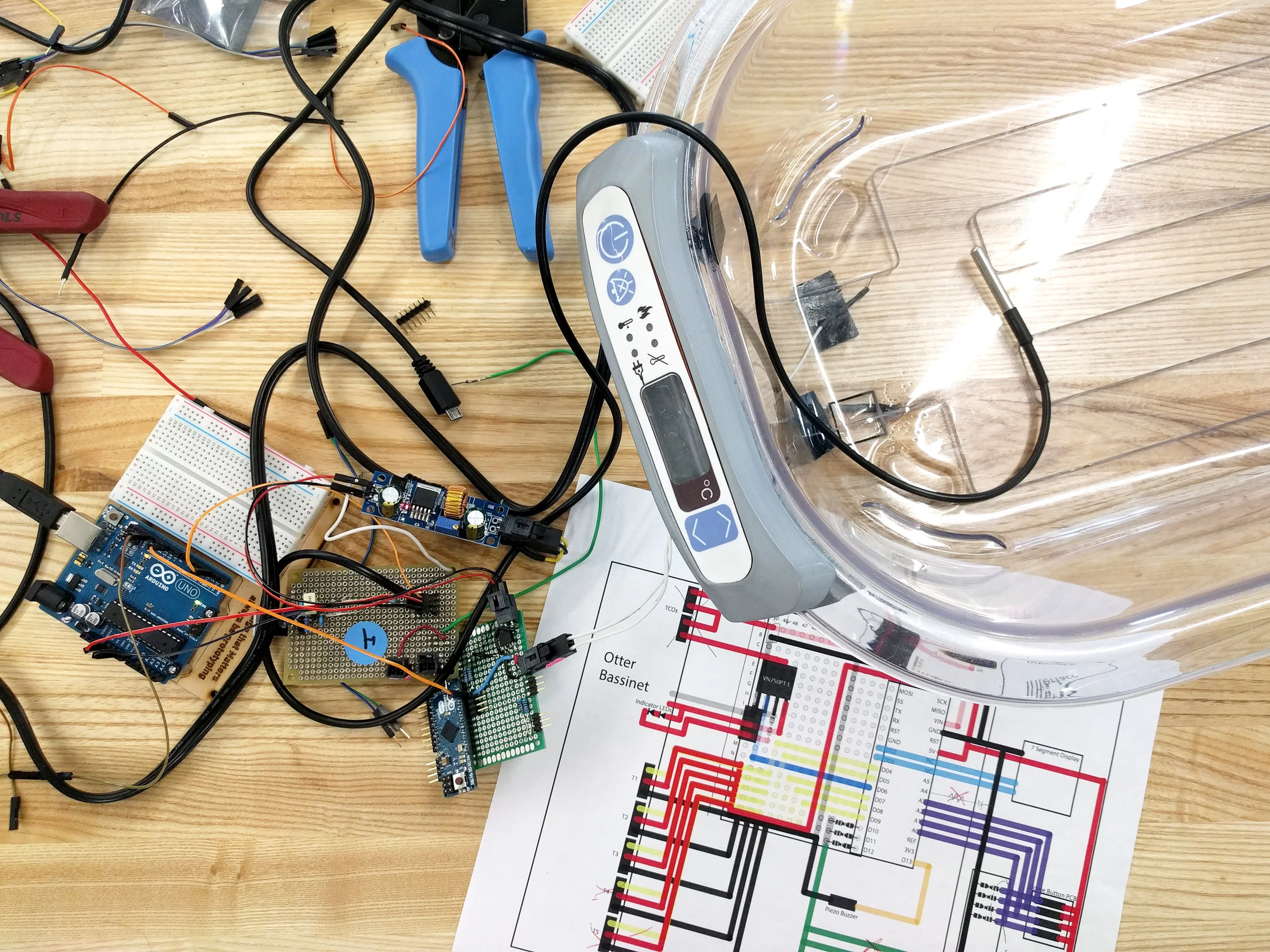
Once everything is mounted, we hooked it up to the main control circuit, used arduino code to coordinate what each button does and when to turn on the LEDs, and we have a working prototype!

The next step is to cover the circuit board with the graphics panel. This piece is made of 3 layers: one of plain white cardstock, and two of clear adhesive graphics paper. We needed the colors of this switch to match the colors on the Firefly UI. So, we printed out the graphics in various hues and tones until we found the perfect CMYK value.

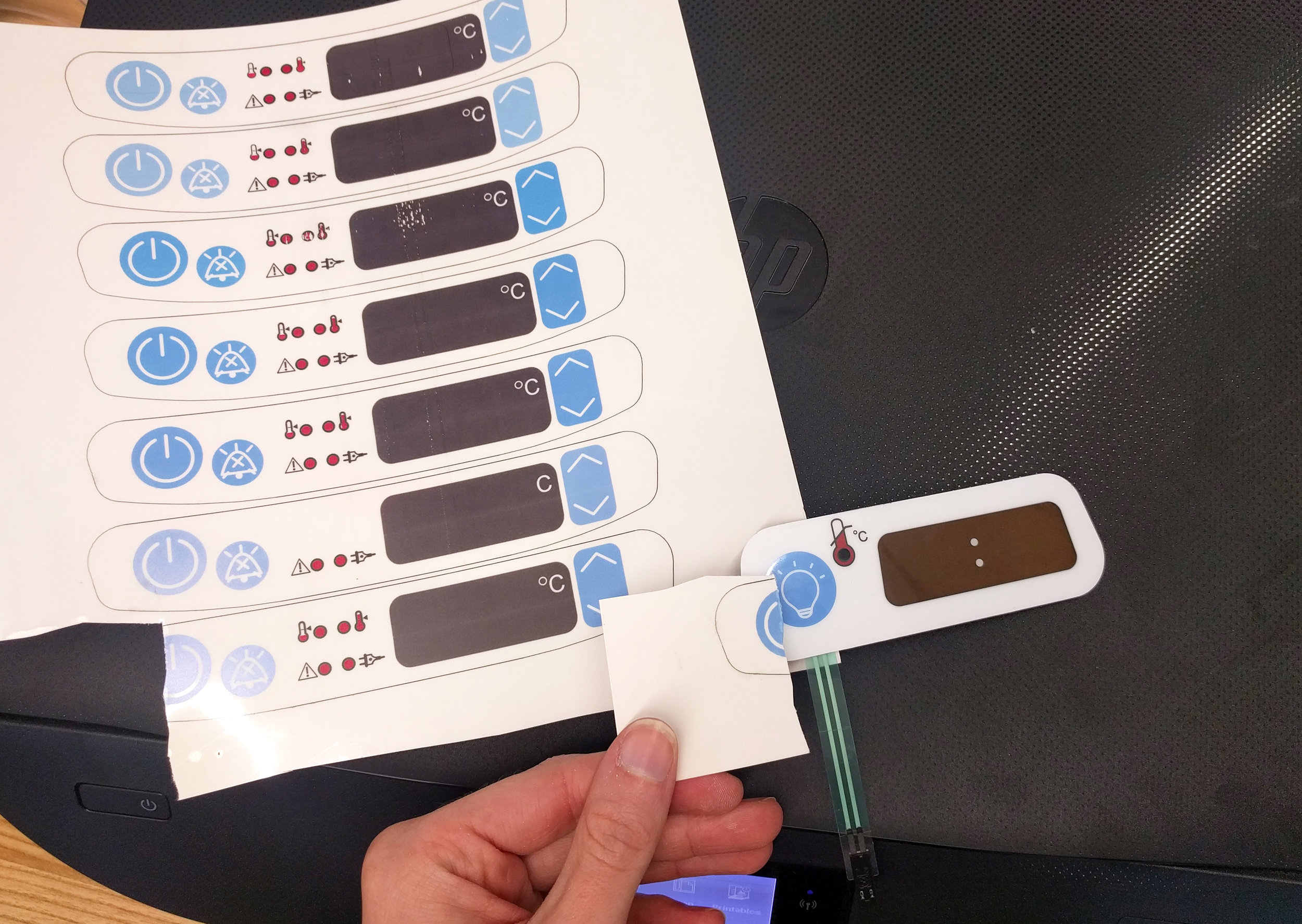
The adhesive graphics paper has a coating on top of acrylic film that accepts the printer’s ink. This material is susceptible to water damage, so to protect the graphics, we sandwiched the printed layer with another layer of the same material, unprinted. We then rubbed off the top coating, leaving a strong, clear acrylic top coat.
Since we don’t have the equipment to print white ink, we took to the laser cutter. We used a piece of white cardstock for extra structure, and cut out the shape of the membrane switch. We aligned and sealed the cut cardstock to the printed graphics, and used the cardstock as a guide to trim the excess.
Lastly, we used a thick coating of Super77 spray adhesive all over the panel’s back and adhered it to the circuit board. This completed the prototype!